Home / News / Industry News / How Heavy-Duty Rotomolded Components Are Engineered for Marine, Traffic, and Industrial Infrastructure
Industry News
Home / News / Industry News / How Heavy-Duty Rotomolded Components Are Engineered for Marine, Traffic, and Industrial Infrastructure
How Heavy-Duty Rotomolded Components Are Engineered for Marine, Traffic, and Industrial Infrastructure
Rotational molding has become the dominant process for large, hollow, seamless plastic components that must endure salt water, UV radiation, vehicle impacts, and chemical exposure. Three product families sit at the center of global demand: marine navigation buoys, road barricades, and industrial storage tanks. Each demands a different mold geometry, wall-thickness strategy, and resin formulation. This article breaks down the engineering decisions that separate a reliable rotomolded part from a field failure.
The Rotomolding Process: Core Mechanics That Drive Product Quality
Rotomolding loads powdered or liquid resin into a closed mold, then rotates the mold simultaneously on two perpendicular axes inside a heated oven. Because there is no internal pressure during forming, the process produces zero residual stress in the finished wall — a critical advantage for parts that must resist cyclic loading, impact, and thermal cycling over a 10-to-20-year service life.
Biaxial Rotation and Even Coating
The ratio of primary-axis to secondary-axis rotation speed — typically a gear ratio between 4:1 and 8:1 — controls how powder distributes across complex mold geometries. A navigation buoy hull with deep re-entrant curves requires a lower ratio than a flat-walled barricade panel. Getting this wrong causes thin spots, the leading root cause of premature cracking in marine applications.
01
Load
Weighed resin charge loaded into open mold halves. Charge weight directly sets finished wall thickness.
02
Heat
Oven temperatures 260°C to 370°C for LLDPE; oven time controls melt quality and wall density.
03
Rotate
Biaxial rotation distributes melt across all inner surfaces; ratio tuned per mold geometry.
Release coating and draft angles of 1°–3° on vertical walls allow clean part separation.
Why Seamless Construction Matters
Unlike blow molding or injection molding, rotomolding produces a single continuous shell with no parting-line weld that could delaminate under pressure. For a marine buoy anchored in tidal zones, or a water storage tank holding thousands of liters, this absence of internal seams is the primary leak-prevention mechanism — not a cosmetic detail.
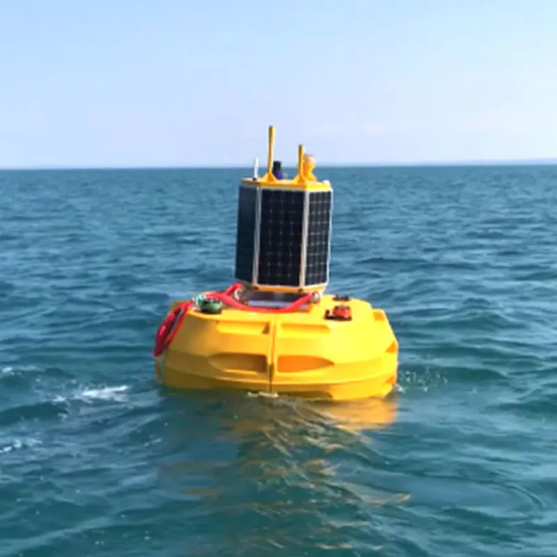
Navigation Buoy Mold Engineering: Surviving the Marine Environment
Navigation buoys are among the most demanding rotomolded products manufactured at industrial scale. A channel-marker buoy may be moored in water for three to five years between maintenance cycles, subject to biofouling, UV degradation, wave surge loads, and vessel impact. The navigation buoy rotational mold must therefore guarantee consistent wall thickness, foam-filling geometry, and hardware-insert locations across hundreds of production cycles.
Hull Geometry and Hydrodynamic Stability
Buoy hull design balances two competing demands: a low center of gravity for upright stability, and sufficient freeboard for visual and radar reflectivity. Standard pillar buoys used in international waterways typically carry a hull diameter of 600 mm to 1,800 mm, a draft-to-freeboard ratio near 2:1, and a mooring-chain attachment plate integrated flush with the base.
In independent buoy stability testing, hull wall uniformity within plus or minus 10 percent of nominal thickness reduced capsize incidents by more than 40 percent compared with buoys showing greater wall variation.
Wall Thickness Targets for Marine Buoys
Buoy Class
Outer Diameter (mm)
Nominal Wall (mm)
Min. Wall (mm)
Foam Core
Small Channel Marker
400–600
8–10
6.5
Optional
Standard Pillar Buoy
800–1,200
10–14
8
Required
Large Cardinal/Special Mark
1,400–1,800
14–18
11
Required
Offshore Mooring Buoy
2,000+
18–25
15
Required (high-density)
Mold Material and Foam-Fill Integration
Buoy molds are most commonly fabricated from cast aluminum (A356 or equivalent) for runs below 500 cycles, and from fabricated or cast steel for high-volume programs. Cast aluminum offers thermal conductivity of roughly 160 W/m·K versus 50 W/m·K for steel — shortening cycle times by 12 to 18 percent. Buoys rated for permanent offshore deployment are filled with closed-cell polyurethane or polyethylene foam (32 kg/m3 to 64 kg/m3) after the shell is formed. Mold designs must accommodate foam-injection ports at 25 mm to 40 mm diameter to ensure complete cavity fill without voids.
Road and construction barricades must satisfy traffic-safety regulations, handle repeated low-speed vehicle impacts without structural failure, and remain cost-competitive for large procurement programs. The barricade rotational mold is typically a matched-pair aluminum tool that produces a hollow shell designed to be filled with water or sand ballast on-site, providing both portability and mass.
Regulatory Geometry and Impact Class
In markets following MUTCD standards, Type III barricades require a minimum height of 900 mm with reflective striping panels no narrower than 150 mm. European EN 13422 specifications define impact-absorption classes from IM1 (pedestrian zone) through IM4 (highway median). Rotomolded barricades are typically validated to IM2 or IM3 — they deform predictably on impact and spring back, rather than shattering into dangerous shards.
150 L
Max ballast capacity, heavy-duty Type III barricade
6–9 mm
Nominal wall thickness for highway-rated barricades
25,000+
Production cycles from a well-maintained aluminum mold
-40°C to +70°C
Operational temperature range for UV-stabilized LLDPE barricades
Water-Ballast Cavity and Parting Line Strategy
The water-fill cavity must hold 50 to 150 liters, drain completely for transport via a base-mounted insert-molded plug, and must not develop stress cracks at the fill-port boss under repeated cycles. Boss wall reinforcement — achieved by locally increasing the powder charge weight — typically adds 3 to 5 mm of extra wall thickness around the port. Placing the parting line on the narrow side edges — rather than across the wide face — minimizes flash on the reflective panel surfaces where appearance matters for safety compliance.
Through-Body Color vs. Post-Mold Painting
Rotomolded barricades produced with orange or red pigment dispersed uniformly through the LLDPE charge maintain their color even after surface abrasion — a key lifecycle advantage over painted steel equivalents. Pigment loading is typically 2 to 4 percent by weight; higher loading slightly reduces impact strength and must be balanced against the UV-stabilizer package already present in the compound.
Water Tank and Storage Container Mold Engineering: Structural Integrity at Scale
Industrial water and chemical storage tanks produced by rotomolding range from 200-liter potable-water containers to 50,000-liter agricultural or process vessels. The water tank storage container mold presents the most demanding structural engineering challenge in the rotomolded product family: hydrostatic pressure acts continuously on the full vessel wall, fittings must remain leak-free for decades, and food-grade or chemical-resistance certifications may apply.
Wall Thickness and Fitting Boss Design
A 10,000-liter vertical cylindrical tank 2,400 mm in diameter filled to 2,400 mm depth exerts roughly 23.5 kPa of hydrostatic pressure at the base. Real-world molds target 10 to 16 mm wall thickness at the base to account for nonuniformity, long-term creep, and fitting boss loads. Boss wall thickness should be at least 1.5 times nominal tank wall thickness, and the transition radius from boss to tank wall should be no less than 25 mm to minimize stress concentration.
highest at base — wall thickness increases toward bottom
Baffles, Certifications, and Chemical Resistance
Tanks exceeding 5,000 liters mounted on transport vehicles require internal baffles to prevent liquid surge from destabilizing the vehicle. Integral baffles formed during the molding cycle eliminate the risk of baffle detachment — a failure mode common in baffles welded in as a secondary operation. Potable-water tanks must be manufactured from resins complying with NSF/ANSI 61 or equivalent national standards, requiring verified pigment systems as well as food-grade resin grades. Chemical storage tanks for acids, alkalis, or hydrocarbons require compatibility testing via ASTM D1693 (environmental stress cracking) and ASTM D638 (tensile after immersion).
Resin Selection Across All Three Product Families
The overwhelming majority of rotomolded infrastructure products are manufactured from linear low-density polyethylene (LLDPE) or cross-linked polyethylene (XLPE). Material choice fundamentally determines which product categories a given mold can serve.
Property
LLDPE Standard
LLDPE UV-Stabilized
XLPE
HDPE
Density (g/cm3)
0.930–0.940
0.930–0.940
0.935–0.945
0.950–0.965
Impact Resistance
High
High
Very High
Moderate
Chemical Resistance
Good
Good
Excellent
Very Good
UV Stability (no additive)
Poor
Excellent
Poor
Poor
Primary Applications
Tanks, barricades
Buoys, outdoor tanks
Chemical tanks
Rigid containers
Typical Oven Temp (°C)
300–340
300–340
330–370
310–350
UV-Stabilizer Packages for Outdoor Products
Marine buoys and outdoor barricades experience cumulative UV exposure equivalent to several thousand hours of xenon-arc testing per year in tropical or high-altitude deployments. A well-formulated UV-stabilizer package combines:
Hindered Amine Light Stabilizers (HALS): scavenge free radicals formed by UV absorption, delaying chain scission and surface chalking.
UV Absorbers (UVA): benzophenone or benzotriazole compounds that convert UV energy to heat before it reaches the polymer chain.
Carbon Black (2–2.5% loading): provides extremely cost-effective UV shielding for black-colored products; absorbs broadly across the UV spectrum.
Products stabilized with a combined HALS-UVA package typically retain greater than 80 percent of original impact strength after 5,000 hours of accelerated weathering (ASTM G154 or ISO 4892-2).
Mold Manufacturing and Maintenance: The Hidden Determinant of Part Quality
Even a perfectly formulated resin charge will produce defective parts if the mold is dimensionally incorrect, thermally uneven, or inadequately maintained.
Mold Materials Compared
Cast Aluminum: Thermal conductivity 150–170 W/m·K; cycle time advantage 15–20 percent over steel; suitable for complex buoy hull geometries; cavity weld-repairs are more difficult than steel.
Fabricated Steel: Lower material cost; easier to weld-repair; heavier, affecting arm loading; slower heat transfer increases cycle time; preferred for very large tank molds.
Electroformed Nickel: Ultra-fine surface reproduction; used for barricades requiring sharp reflective-panel detail; high tooling cost limits use to high-volume programs.
Vent Placement and Release Coating
As LLDPE melts and consolidates, it releases moisture and volatile compounds. Without properly placed vents, these gases produce surface pinholes and internal voids. Vent tubes of 6 to 10 mm diameter are placed at the highest point of the mold in each rotational orientation — typically 3 to 6 vents per mold half for complex geometries like buoy hulls. Internal mold surfaces are coated with semi-permanent PTFE-based release systems applied every 15 to 50 shots, significantly reducing labor cost versus traditional wax systems requiring re-application each cycle.
1
Inspect cavity surface every 500 cycles; photograph and log pitting, corrosion, or dimensional change
→
2
Polish high-wear areas (parting line, boss transitions) with progressively finer abrasives to 600 grit
→
3
Apply semi-permanent release coat; cure per specification before returning to production
→
4
At 5,000-cycle intervals: dimensional audit against CAD; weld-repair or re-machine if outside tolerance
Quality Control Methods for Rotomolded Infrastructure Products
Wall Thickness and Impact Testing
Ultrasonic thickness gauges using 5 to 10 MHz transducers are the standard non-destructive method for verifying wall uniformity. A competent QC program maps at least 20 measurement points per buoy hull following a defined grid; any point more than 20 percent below nominal triggers rejection. Impact resistance is temperature-dependent — a part passing room-temperature drop testing may fail at -20°C. For buoys deployed in Arctic waters, Charpy notched impact values at -40°C must meet minimum thresholds from product specifications. Test specimens cut from actual production parts are more representative than test plaques, because the thermal history during the mold cycle affects crystallinity and toughness.
Hydraulic Pressure Testing for Tanks
Storage tanks are proof-tested at 1.3 to 1.5 times maximum working pressure, filling to 150 percent of rated depth with water and holding for 24 hours while inspecting for weepage, joint deflection, or permanent deformation at fittings. Any measurable leakage at a boss fitting constitutes a reject.
Frequently Asked Questions
Q1: What wall thickness should a rotomolded navigation buoy have for offshore mooring service?
For offshore mooring buoys with outer diameters of 1,400 mm or larger, a nominal wall thickness of 14 to 18 mm is recommended, with a minimum acceptable reading of 11 mm at any point. Foam filling is mandatory at this size to ensure positive reserve buoyancy even if the outer shell sustains minor impact damage. High-energy wave environments should target the upper end of the range.
Q2: How many production cycles can an aluminum barricade mold achieve before major refurbishment?
A well-maintained cast aluminum barricade mold typically achieves 20,000 to 30,000 production cycles before requiring dimensional restoration. The parting line and drain-plug boss areas wear fastest, requiring weld build-up and re-machining at 8,000 to 12,000 cycles. Steel molds generally reach 50,000 or more cycles before major refurbishment, at the cost of slower cycle times and higher energy consumption per part.
Q3: What resin is best for a rotomolded tank storing agricultural chemicals?
Cross-linked polyethylene (XLPE) is the preferred choice for agricultural chemical storage, particularly for fertilizer solutions, herbicides, and pesticides that could cause environmental stress cracking in standard LLDPE. XLPE provides superior ESCR because the cross-linked network prevents polymer chain mobility in the presence of aggressive surfactants. Always verify resin compatibility against the specific chemical using ASTM D1693 data from the resin supplier.
Q4: Can UV-stabilized rotomolded products be used in tropical equatorial deployments?
Yes, but the UV-stabilizer package must be specified for the actual solar irradiance at the deployment site. Equatorial locations receive approximately 30 to 40 percent higher annual UV dose than temperate locations. Specify a combined HALS-UVA stabilizer at the upper loading range, and carbon black pigmentation where acceptable. Expected service life with a properly formulated compound is 10 to 15 years outdoors.
Q5: What is the typical lead time for a custom rotomolding mold for a large storage tank?
Cast aluminum molds for tanks up to 5,000 liters typically require 8 to 14 weeks from approved drawing to first-shot trial. Fabricated steel molds for the 10,000 to 50,000 liter range may require 14 to 22 weeks. Integrated baffles, fitting boss count, and surface texturing all extend lead time. First-article qualification testing adds 3 to 6 additional weeks.
Q6: How is wall-thickness uniformity controlled during the rotomolding cycle?
Wall uniformity is controlled through three primary variables: the biaxial rotation speed ratio, oven temperature profile (uniformity within plus or minus 5°C across the mold surface), and precise resin charge weight. Advanced operations use internal air-temperature monitoring via thermocouple probes through vent tubes to detect the inflection in the cooling curve that signals complete sintering — removing the part before this inflection results in pinholes and low-density walls.
 en
en