 en
en 中文简体
中文简体 русский
 Español
 Deutsch
 Polskie
 REQUEST A QUOTE

 Home / News / Industry News / How Rotational Mold Tooling Design Controls Tolerances and Prevents Defects
 How Rotational Mold Tooling Design Controls Tolerances and Prevents Defects
Content
- 1 Tooling Material Choices That Shape Part Quality
- 2 What Determines Achievable Rotational Molding Tolerances
- 3 Nominal Wall Thickness and Corner Radii: Where Most Defects Originate
- 4 Draft Angles Optimization for Reliable Part Release
- 5 Troubleshooting Common Rotomolding Defects
- 6 Tooling Maintenance Practices That Preserve Tolerance Over Time
- 7 Frequently Asked Questions
- 7.0.1 Q1: How does mold material affect rotational molding tolerances?
- 7.0.2 Q2: What nominal wall thickness is typical for outdoor panel-style parts?
- 7.0.3 Q3: Why do corner radii matter more in rotational molding than in other processes?
- 7.0.4 Q4: What is a reasonable draft angle for a lightly textured surface?
- 7.0.5 Q5: Can rotomolding defects like pinholes be fully eliminated?
Tooling Material Choices That Shape Part Quality
The starting point for any rotomolded part is the mold itself. Tooling material governs how fast heat transfers, how tight the achievable tolerances are, and how many cycles the tool can run before dimensional drift sets in. Two approaches dominate the industry: rotational mold tooling machined from solid aluminum billet, and fabricated steel shells built from sheet metal.
Practical note: A decorative garden piece such as a rockery fence rotational mold is a good example of a geometry that benefits from CNC-machined tooling, since textured stone-like surfaces and consistent panel-to-panel matching depend on repeatable cavity dimensions.
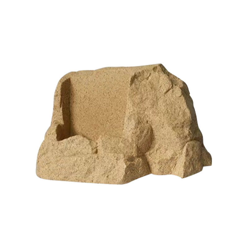
Aluminum offers thermal conductivity roughly three to five times higher than mild steel of comparable thickness, which shortens heating and cooling segments in the oven cycle and reduces the chance of localized overheating that leads to scorching or internal bubbling. Fabricated steel remains common for very large tanks and simple geometries where machining costs would be disproportionate to part complexity.
| Attribute | CNC Machined Aluminum Molds | Fabricated Steel Tooling |
|---|---|---|
| Typical wall tolerance | Plus or minus 0.4 to 0.6 mm | Plus or minus 1.0 to 1.5 mm |
| Surface detail capability | High, including fine texture | Moderate, limited by weld seams |
| Lead time for complex shapes | Shorter once CNC program is set | Longer due to hand fabrication |
| Best fit | Small to mid-size, detailed parts | Large tanks, simple silhouettes |
What Determines Achievable Rotational Molding Tolerances
Rotational molding tolerances are never a single fixed number; they scale with part size, wall thickness target, and mold construction quality. As a general guide, dimensional tolerance widens as the distance from a reference datum increases, since powder flow and shrinkage variation accumulate over larger spans.
- Linear dimensions under 300 mm typically hold plus or minus 0.5 percent of the nominal dimension
- Dimensions between 300 mm and 1000 mm typically hold plus or minus 0.8 to 1.0 percent
- Dimensions above 1000 mm often require plus or minus 1.2 percent or a fixture-based secondary check
Because polyethylene resins shrink as they crystallize during cooling, the mold cavity is intentionally machined oversized relative to the finished part. Shrinkage allowances commonly fall between 1.5 percent and 3.5 percent depending on resin grade and wall thickness, and this figure must be locked in before the tool is cut, since it cannot be corrected afterward without re-machining.
Nominal Wall Thickness and Corner Radii: Where Most Defects Originate
Nominal wall thickness is the target thickness specified for the majority of the part surface, and it is the single variable most responsible for cycle time, strength, and warpage resistance. Thin sections cool faster than thick sections, so any geometry mixing both will experience differential shrinkage unless corner radii are managed carefully.
A widely used design rule sets the minimum inside corner radius equal to the nominal wall thickness, and outside radii slightly larger still. Radii smaller than this cause powder to accumulate unevenly during rotation, leaving thin webbing at the corner that becomes the first point of cracking under load or thermal cycling.
| Nominal Wall Thickness | Recommended Minimum Inside Radius | Recommended Minimum Outside Radius |
|---|---|---|
| 3.0 mm | 3.0 mm | 4.5 mm |
| 4.5 mm | 4.5 mm | 6.0 mm |
| 6.0 mm | 6.0 mm | 8.0 mm |
Draft Angles Optimization for Reliable Part Release
Draft angle is the taper applied to vertical mold walls that allows a cooled part to release without scraping, tearing, or deforming. Because rotomolded parts have no injection pressure pushing plastic against the cavity, draft requirements differ from injection molding and are driven mainly by surface texture and part depth.
- Smooth cavity walls generally need a minimum draft of about 1 degree
- Light texture finishes typically require 2 to 3 degrees
- Heavy textures, such as stone or wood-grain effects, often need 5 degrees or more
- Deep ribs or standoffs benefit from additional draft beyond the surrounding wall to avoid drag marks
Insufficient draft is one of the most frequent causes of warped panels reported after demolding, because forcing a part free of an undersized taper introduces asymmetric stress before the material has fully stabilized dimensionally.
For textured tooling, draft should be measured from the base of the texture pattern rather than from the nominal wall surface, since deep texture effectively reduces the usable taper by several tenths of a degree per side.
Troubleshooting Common Rotomolding Defects
Most rotomolding defects trace back to one of three variables: heat distribution, powder behavior, or mold condition. The flow below outlines a practical diagnostic sequence for the two most reported issues.
| Defect | Likely Cause | Corrective Action |
|---|---|---|
| Pinholes | Trapped air or moisture in powder | Dry resin before use, verify vent function |
| Warpage | Uneven wall thickness or cooling rate | Balance airflow, add ribbing at transitions |
| Bridging at corners | Radius too tight for wall thickness | Increase corner radius per design table |
| Surface pitting | Contaminated mold release or dust | Clean cavity, filter release agent |
Tooling Maintenance Practices That Preserve Tolerance Over Time
Even a well-machined mold will drift out of tolerance if maintenance is neglected. Repeated thermal cycling loosens fasteners, wears parting line seals, and can gradually distort thin aluminum shells if support framing is inadequate.
- Inspect parting line fit after every 200 to 300 cycles for early gap formation
- Re-torque frame and clamp fasteners on a fixed schedule rather than waiting for visible leakage
- Track vent tube cleanliness, since blocked vents are a repeat cause of pinhole recurrence
- Log cavity temperature readings across multiple points to catch uneven heating before it affects parts
Field observation: Molds that receive scheduled parting line inspection typically hold rated tolerance bands twice as long between refurbishment cycles compared with molds inspected only after a defect appears.
Frequently Asked Questions
Q1: How does mold material affect rotational molding tolerances?
Aluminum tooling generally supports tighter tolerances because it heats and cools more evenly than fabricated steel, reducing the localized expansion differences that cause dimensional drift.
Q2: What nominal wall thickness is typical for outdoor panel-style parts?
Many outdoor panel and enclosure parts use a nominal wall between 4 mm and 6 mm, balancing impact resistance with reasonable cycle time and material cost.
Q3: Why do corner radii matter more in rotational molding than in other processes?
Because rotomolding relies on gravity and rotation rather than injection pressure to distribute powder, sharp corners are naturally under-filled, making a generous radius essential for even wall buildup.
Q4: What is a reasonable draft angle for a lightly textured surface?
A range of 2 to 3 degrees is common for light texture, though deeper textures should be measured from the texture base and may need additional draft.
Q5: Can rotomolding defects like pinholes be fully eliminated?
They can be greatly reduced through resin drying, vent maintenance, and stable oven temperatures, though isolated pinholes may still occur with any powder-based process.

We provide customers with one-stop services ranging from product design, mold manufacturing to finished product production.
-
 +86-18006248936
 -
 ricky.t@zhroto.com
 -
 No.9 Jiangyuan Road, Luotang Street, Jiangyan District, Taizhou City,Jiangsu Province, China
Copyright © Jiangsu Zhroto Mould Co., Ltd. Rights Reserved.Custom Rotational Plastic Molding Factory
