 en
en REQUEST A QUOTE

 Home / News / Industry News / How Resin Choice and Process Control Determine Rotomolding Part Quality
 How Resin Choice and Process Control Determine Rotomolding Part Quality
Why Resin Selection Defines Rotomolded Part Performance
Every rotationally molded component begins as loose powder inside a closed cavity, long before it takes on the shape of a tank, enclosure, or structural housing. Because the process relies on gravity and heat rather than injection pressure, the behavior of the resin itself carries far more weight than in most other plastics processes. A resin with poor melt flow at the target oven temperature leaves pinholes and weak knit lines, while a resin with the wrong impact profile turns brittle the first winter it spends outdoors.
Rotomolding resin is typically supplied as a fine powder rather than pellets, since powder melts and coats the mold interior more evenly during the slow, low shear rotation cycle. The three material families that dominate industrial and agricultural applications are standard HDPE, cross-linked polyethylene, and nylon, each suited to a distinct set of mechanical and environmental demands.
Key point: Resin selection should be driven by the part's service environment first, and its shape or wall thickness second. A tough resin poorly matched to UV exposure or chemical contact will fail regardless of how well the mold was tooled.
HDPE, Cross-Linked Polyethylene, and Nylon: Matching Resin to Application
Standard HDPE rotomolding grades remain the default choice for general purpose tanks, bins, and covers because of their balanced cost, processability, and chemical resistance. Cross-linked polyethylene, commonly abbreviated XLPE, undergoes a chemical bonding reaction during or after the melt cycle that links polymer chains together, producing higher environmental stress crack resistance and better creep performance under sustained load. Nylon, while more difficult to process due to its narrower melt window and moisture sensitivity, offers markedly higher stiffness, abrasion resistance, and temperature tolerance, making it a candidate for parts that see mechanical wear or contact with fuels and solvents.
| Property | Standard HDPE | Cross-Linked PE (XLPE) | Nylon |
|---|---|---|---|
| Impact resistance at low temperature | Good | Very good | Moderate |
| Chemical and stress crack resistance | Moderate | High | High |
| Typical service temperature ceiling | 60 to 70 C | 70 to 80 C | 100 C and above |
| Processing difficulty | Low | Moderate | High |
| Relative material cost | Low | Moderate | High |
| Common use case | Tanks, bins, housings | Load bearing covers, fuel tanks | Gears, wear plates, bushings |
The decision rarely comes down to a single property. A cover panel exposed to constant flexing and UV load may perform better in cross-linked polyethylene even though standard HDPE is cheaper, because the cost of premature cracking and replacement outweighs the material premium over the part's service life.
Resin Powder Mesh Size and Wall Thickness Consistency
Rotomolding resin is ground to a specific particle size distribution, commonly described by mesh size, before it ever reaches the mold. A mesh size around 35 has become a de facto industry reference point because it balances two competing needs: fine enough particles to melt quickly and flow into detailed corners, but not so fine that the powder generates excessive dust, static buildup, or air entrapment during tumbling.
- Coarser powder grinds melt more slowly and can leave visible unmelted specks or a rougher interior surface.
- Overly fine powder increases the risk of trapped air bubbles, since fine particles pack more tightly and release gas less easily during the melt phase.
- Inconsistent particle size distribution within a single batch causes uneven melt progression, which shows up as thin spots at corners and thick buildup in flat areas.
Because wall thickness variation is one of the most common warranty complaints in rotomolded parts, many processors now sieve incoming resin lots and track particle size distribution alongside bulk density as a routine incoming quality check, rather than relying on the resin supplier's certificate alone.
Calculating and Applying the Rotational Molding Speed Ratio
The rotational molding speed ratio describes the relative rotation speed between the major and minor axes of the machine arm, usually expressed as a ratio such as 4 to 1 or 8 to 1. This ratio, together with the part geometry, determines how evenly the melted resin distributes itself across the mold surface as gravity pulls it around during each rotation.
| Speed ratio | Typical part shape | Effect on wall distribution |
|---|---|---|
| 1 to 1 | Spheres, simple symmetric shapes | Even coating with minimal correction needed |
| 3 to 1 or 4 to 1 | Rectangular tanks, boxes | Reduces thin corners on the long axis |
| 6 to 1 or higher | Long, narrow, or asymmetric parts | Prevents pooling at one end during the cycle |
Getting the ratio wrong produces predictable defects. A ratio that is too low on an elongated part allows resin to accumulate at the ends before it fully melts, leaving the middle section thin. A ratio that is too aggressive on a compact part can strip resin away from flat panel areas faster than it deposits, leading to uneven buildup opposite the strip zone. Mold designers typically start from published reference ratios for similar geometries, then fine tune based on wall thickness measurements taken from early production samples.
Oven Heating Cycle Optimization for Uniform Melt
The oven cycle is where the powder actually becomes a coherent plastic shell, and its optimization depends less on air temperature alone than on tracking the internal air temperature inside the mold cavity, often referred to as IAT monitoring. Oven air temperature is simply the input; internal air temperature reflects how much heat has actually transferred through the mold wall and into the resin.
- Preheat phase: mold surface warms and initial powder tack begins, preventing the charge from sliding as a loose mass.
- Melt phase: powder particles fuse together and coalesce into a continuous film across the mold interior.
- Densification phase: trapped air pockets migrate out of the melt and the wall becomes visually clear and void free.
Processors who monitor peak internal air temperature rather than relying purely on a fixed oven time consistently report fewer bubble related rejects, because cycle time can then be adjusted for seasonal changes in ambient temperature, mold wall thickness, or resin batch variation, instead of running every cycle to a worst case timer.
Cooling Rate Control and Warpage Prevention
Cooling is frequently treated as a passive step, but the rate and uniformity of cooling has a direct effect on internal stress, shrinkage, and final dimensional accuracy. Polyethylene and nylon both shrink as they cool from the melt, and if one region of a part cools faster than another, the resulting stress differential pulls the part out of shape after demolding, sometimes hours later once residual stress fully relaxes.
| Cooling method | Relative speed | Typical risk if misapplied |
|---|---|---|
| Ambient air only | Slow | Long cycle time, minimal warp risk |
| Forced air | Moderate | Uneven cooling if airflow is not balanced around the mold |
| Water mist or spray | Fast | Surface sink marks or internal stress if applied too early |
A common rule followed by experienced operators is to allow the outer skin to solidify under slower ambient or light forced air cooling before introducing faster water cooling, since quenching a still soft surface tends to lock in stress rather than release it. Thick sectioned parts, such as reinforced mounting bosses, require particular attention because they retain heat far longer than surrounding thin wall areas.
Mold Release Agents and Surface Finish Quality
Release agent choice affects both demold reliability and the final cosmetic surface. Semi-permanent release coatings are baked onto the mold surface and last for multiple production cycles before reapplication, making them common in higher volume runs. Sacrificial release agents are applied before every single cycle and burn off during the oven phase, offering more consistent release performance on textured or deeply ribbed cavities at the cost of added labor per cycle.
Buildup of release agent residue over repeated cycles is a frequent, underappreciated cause of gradual surface finish drift, where parts that looked acceptable early in a production run start showing dull patches or minor surface pitting weeks later. Scheduling periodic mold cleaning alongside release reapplication helps keep finish quality consistent across long production runs.
Applying These Controls to an Agricultural Machinery Parts Mold
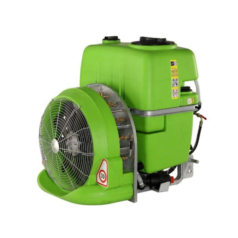
An agricultural machinery parts mold presents a demanding combination of the issues covered above in a single tool. Farm equipment components are typically exposed to sustained UV, temperature swings between a cold morning and a hot afternoon, vibration from engine and drivetrain contact, and occasional impact from field debris, all while carrying mounting bosses and rib patterns that vary wildly in wall thickness across a single part.
Because these parts combine thin shell sections with thick reinforced mounting points, oven cycle timing has to be set by the thickest section rather than the average wall, or the mounting bosses will remain undercured while the surrounding shell is already fully densified. Cooling then has to be staged carefully, since those same thick bosses retain heat well after the thin shell has already set, and rushing water cooling at that stage is a common cause of warped mounting flanges that no longer align with the equipment they were designed to fit.
Tooling decisions made early in the design of custom mold cavities for agricultural component housings also influence how forgiving the process will be later. Rounded internal corners, gradual thickness transitions, and vent placement away from thick sections all reduce the sensitivity of the finished part to small variations in oven time or rotation ratio, which matters when a mold runs across different plants or shifts with different operators.
Processors setting up new tooling for this category often benefit from treating the first several production cycles as a diagnostic exercise, cross sectioning early samples to check wall thickness distribution before committing to a fixed cycle recipe for rotational molding tooling for farm equipment enclosures, rather than assuming the first working cycle is the optimal one.
Process Flow at a Glance
The diagram below summarizes how the stages described above connect within a single production cycle, from raw powder charge through to a finished, demolded part.
Frequently Asked Questions
Q1: What resin is best for a part that stays outdoors year round?
Cross-linked polyethylene is generally favored over standard HDPE for continuous outdoor exposure because of its higher resistance to environmental stress cracking, though the added processing complexity should be weighed against the expected service life requirement of the part.
Q2: How does mesh size affect wall thickness variation?
Finer or coarser mesh sizes than the resin was designed for change how quickly and evenly the powder melts, which shows up as inconsistent wall thickness even when the oven cycle and rotation ratio remain unchanged.
Q3: Why does a part warp after it looks fully cooled?
Residual internal stress from uneven cooling can continue to relax for hours after a part feels cool to the touch, which is why dimensional checks are usually more meaningful after a full stabilization period rather than immediately after demolding.
Q4: Does a higher speed ratio always improve wall uniformity?
No, an excessively high ratio for a compact or symmetric part can strip resin away from flat areas faster than it can build up, so the ratio needs to match the specific part geometry rather than defaulting to the highest available setting.
Q5: How often should release agent be reapplied?
This depends on whether a semi-permanent or sacrificial system is used; semi-permanent coatings can last multiple cycles but should be inspected regularly for wear, while sacrificial agents are typically reapplied before every cycle.
We provide customers with one-stop services ranging from product design, mold manufacturing to finished product production.
-
 +86-18006248936
 -
 ricky.t@zhroto.com
 -
 No.9 Jiangyuan Road, Luotang Street, Jiangyan District, Taizhou City,Jiangsu Province, China
Copyright © Jiangsu Zhroto Mould Co., Ltd. Rights Reserved.
